Monoblock amplifiers
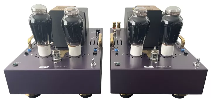
Our goal with the Sapphire was to design an amplifier around what is probably the most known and popular tube for audio use, namely the 300B.
We have replaced the Full Music TJ mesh plate premium Gold 300B previously used with the upgraded Shuguang "A" Treasure 300B-Z. We chose the Shuguang "A" Treasure 300B-Z output tubes for their superior sound and reliability.
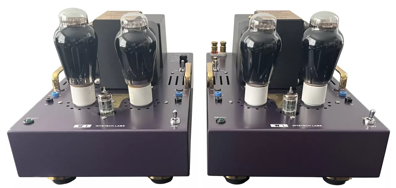
This amplifier also uses another rugged 5687 NOS triode for the voltage & driver gain stages that complements and allows the 300B to perform at its best.
Using a wide bandwidth custom Hammond output transformer has allowed this design to overcome the short comings that a lot of other 300B amplifiers are noted for. You will be surprised to know that the bass is quick, fast and deep, while the highs are smoothly extended to 40 kHz.
Separate high voltage DC power supplies isolate the voltage/driver stages from the output stage, which in a single ended amplifier is a critical attribute.
Our self-biasing stages, while completely eliminating all adjustments, insure long term stability and reliable operation. As in our previous Onyx design, we have implemented what we call a quasi-parallel circuit design where each of the two output triodes have their own independent automatic biasing circuit. Only the plates are tied together to drive the output transformer. Although this doubles the amount of parts in the biasing circuitry that normally would be employed, it results in a purity of sound that one would normally associate when using only a single triode, such as is implemented in our Topaz design.
We also use filtered DC on the filament of the input / driver tube to keep hum and noise at a minimum. The 300B output filaments each have their own regulated DC 5 volt supply that negates the use of hum minimizing adjustments that inferior amplifiers use.
We use large Teflon signal capacitors which are among the best in the world with an unlimited life expectancy due to their indestructibility that results from their self healing attribute which is a feature of their metalized construction.
Further refinement comes with a gold plated brass holder with 3M rubber feet inserts to accentuates the styling and to allow proper air flow for the vents under the chassis
We use a delayed DC power sequencing that maximizes tube life by preventing cathode emission deterioration. Low frequency response has been greatly enhanced by using very large signal capacitors and wide bandwidth custom output transformers. These combined attributes reduce overall distortion at higher power levels and give an overall impression of a much more powerful amplifier than what the specifications would suggest.
Unlike solid state amplifiers, that when clipped sound extremely harsh, this amplifier can be pushed beyond it's rating with little noticeable effect due to the tendency to compress when overdriven, which is much more benign than what normally occurs with solid state equipment.
Design Goals
Audio Circuits
We opted to keep the same circuit topology as that found in our more expensive Topaz amplifier, which is plate loaded single ended in all stages. For the signal and driver we use readily available NOS (New Old Stock) triodes that were made in the USA and have met JAN (Joint Army Navy) military specifications. We chose the Shuguang "A" Treasure 300B-Z output tubes for their superior sound and reliability.
We use a custom Hammond output transformer designed to our specifications which resulted in a wide bandwidth with exceptionally deep low frequency response.
Power Supply
Single ended amps are more susceptible to power supply aberrations than push-pull amps. For this reason we have split the front end from the output by using completely separate power supplies. This eliminates power supply feedback non-linearity. To keep cost moderate and still uphold sound quality we opted for R-C filtering as opposed to the more expensive L-C used in the Topaz. (R = resistor, C = capacitor, L = inductor) We also use electrolytic capacitors with much larger storage capacity to make up for the loss in filtering when using resistors in lieu of inductors. The radiated heat is distributed inside the chassis, such that, it insures that the chassis runs only warm to the touch. The total power intake and heat dissipation is only 185 watts per channel, for an amplifier operating in pure class A1.
Parts Quality
We use precision quality parts throughout. Our Printed Circuit Boards have a manually designed layout using computers to meet the needs of analog design which are radically different than digital or computer circuit design. We needed large signal and power traces and special footprints for parts like the tube sockets. This has resulted in short signal paths and more precise positioning of components on the board. We use wire wound silicone and ceramic high power resistors and computer grade electrolytic capacitors in our power supplies.
All wiring to the printed circuit boards is done with the use of screw down connectors. This is done for ease of repair should ever the need arise. We use a single OFC co-ax cable for the signal input wiring and Teflon coated silver plated OFC wire for the speaker connection and selector impedance switch wiring.
Gallery

Circuit Description
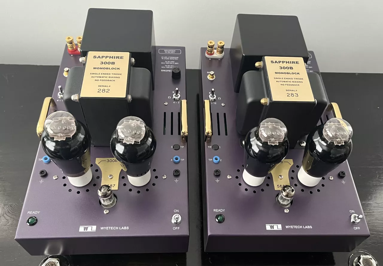
All stages operate in pure class "A1" single ended and contain automatic self-biasing circuitry. We have maintained our Topaz tradition in the use of exceptionally large value Solen polypropylene coupling capacitors. This together with our custom built HAMMOND output transformer has endowed this amplifier with very extended low and high frequency response. Each of the two output triodes are individually self-biased, with only the plates tied together in a quasi parallel configuration, which is nearly equivalent to having one high powered triode. Our 12 pound output transformer provides 18 Watts RMS per mono-block with solid bass and absolute stability into all low impedance loads. The output windings can be toggled via two high current switches to allow selection of impedance for 2, 4, 8 or 12 Ohms. We employ no feedback of any kind due to the low distortion ultra-linear amplification stages employed in this design.
Power Supplies
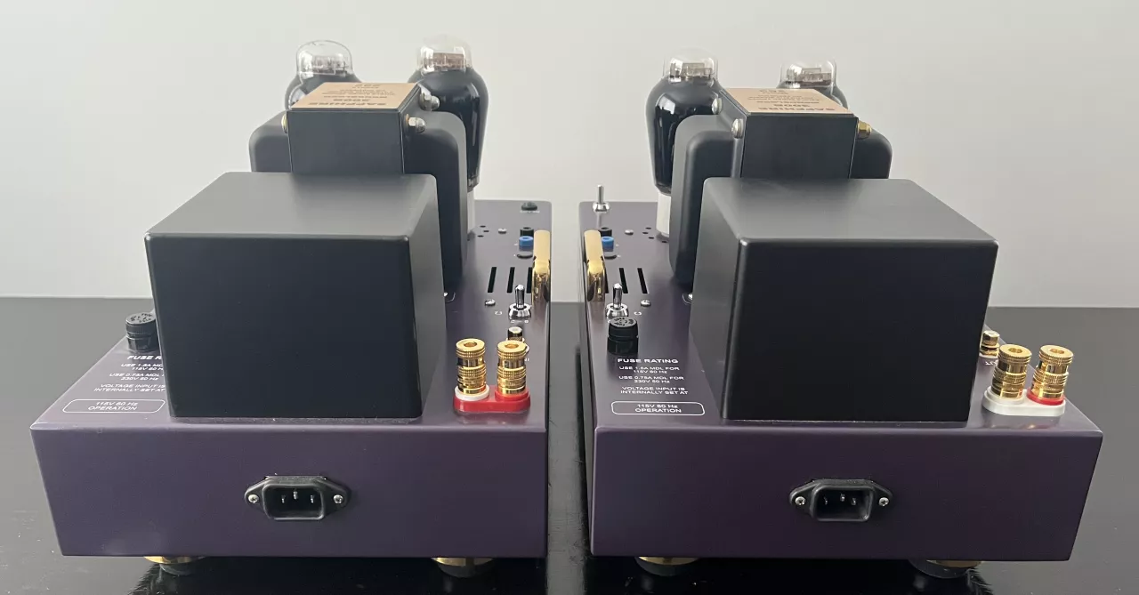
- Toroidal power transformer voltage input can be selected for 115V/230V 50-60 Hz operation via an internal toggle switch. Three output windings provide full-wave rectification using spike & noise suppression circuitry.
- Separate DC power supplies provide total isolation between the INPUT and OUTPUT stages. These consist of a triple π (pi) filter for the 460 Volt output rail and a double π (pi) filter for the 400 Volt input & driver rail. The use of RC filter networks with very large electrolytic capacitors and wire wound power resistors provide an unparalleled ripple reduction and low noise operation.
- Rectified and filtered DC provide the power for the input tube filament of the 1st and 2nd stage. The other two 300B output tube filaments each have their dedicated regulated DC floating power supply that eliminates the normally found hum adjusting potentiometer. This provides a very low noise floor that allow all subtle nuances in the music to be heard.
Mechanical Construction
- Extremely rugged (14 gauge) all welded steel chassis further reduces any possibility of vibration induced signal aberrations.
- Highly polished brass handles allow for easy handling and accentuates the chassis styling.
- Gold plated brass holder with 3M rubber feet inserts accentuates the styling and allows proper air flow for the vents under the chassis
- Teflon Gold plated machined brass (tube pin connectors) 300B sockets for an absolute secure connection and lifetime reliability
- Very high quality paint / primer coat and baked on finish enhance the artistry.
- A deep lavender color accentuates the satin black finish of the output transformer and toroid cover.
- A cast aluminum box is used to cover the power Toroid transformer to strengthen an already appealing look.
Circuit Boards
The components are mounted on a printed circuit board [PCB] which is made from FR4 glass epoxy with double sided copper traces and plated through holes. Both sides have a protective green solder mask. A silkscreen is printed in white showing the component layout and parts value. This PCB was designed manually in house. It has enlarged power and signal line traces to attain the best analog integrity that automatic routing circuit programs cannot attain. Our printed circuit board program allows for an infinite varieties of traces and component layouts that can be developed into our own custom library parts. We have created a library of custom component layouts that are specifically suited to develop our Analog circuits. Wiring to the PCB is attached via screw down crimp terminals to allow for ease of repair should the need ever occur where the board would need to be removed. We have reduced the signal path length to less than 6" on the PCB. The final assembly of parts to the PCB is done by hand soldering of all components, which is superior to automated flow-soldering techniques, by allowing more solder on each and every joint.
Auto-Sequencing
A time-delay relay provides extended tube life and proper power sequencing for stabilized circuitry on power up. The filament voltage is turned on for 45 seconds before applying the DC voltage power, after which the ready (green) LED comes on.
Power Switch
Applies power to the automatic power up sequencing circuit.
Output Load Impedance Selector Switches
These switches allow selection between 2 and 16 ohm speakers. Using a lower setting than the rating of the speakers increases the damping factor which may increase the performance depending on the speaker being used. In general the best overall setting is usually what the speaker is rated for. The 12 Ohm position can be used to drive speakers rated at 12 Ohms and above. To set the proper impedance you need to insure both switches are in their proper position. Each switch setting shows two possible impedance's. The numbers that match from both switch positions tell you what impedance is selected. Thus four selections are possible, which are 2,4,8 and 12 Ohms.
Input Gain Selection
Low = 20dB, Normal = 25dB, High = 30dB
- Normal gain is preset at the factory. To change you must remove the bottom cover.
- Low or Normal gain is selected via a toggle switch on the PCB board. Jumper must be in the IN position.
- High is selected by moving the jumper as shown in diagram from the IN to the OUT position. Switch can be in either position for this setting.
Absolute Phase:
Non-Inverting.
If you have other equipment that inverts the phase, then the easiest way to adjust for absolute phase is to reverse the + and - speaker connector leads.
Output Impedance Matching
- toggle switches enable setting for 2, 4, 8 & 12 Ohms
- matching numbers indicate which impedance is selected
Specifications
Tube Complement
- 1 - Dual triode 9-pin base 5687WB JAN Military NOS - input / driver stage
- 2 - Triode 4 pin-base 300B Shuguang Treasure premium grade - output stage
Frequency Response
+ 0 / - 1 dB > 11 Hz to 28 kHz
+ 0 / - 3 dB > 6 Hz to 43 kHz
Input Impedance
| Impedance | Gain | |
|---|---|---|
| Low | 55 Kohms | 20db > 1.28 VRMS for full output |
| Normal | 50 Kohms | 25db > 0.6 VRMS for full output |
| High | 200 Kohms | 30db > 0.38 VRMS for full output |
Absolute Phase
non-inverting (can be set to Invert at Factory)
Power Output
18 Watts RMS per Channel
Dynamic Headroom
music peaks up to 40 Watts
Energy Storage
300 joules
Universal Voltage Select
115/230 Volts 50/60 Hz
Power Consumption
185 Watts per mono-block
Weight (Net)
2 x 33 lbs. (30 kg)
Weight (Shipping)
2 x 38 lbs. (35 kg)
Dimensions
9.5" W x 16" L x 8.5" H
Reviews
6moons
September 2004 - Reviewed by Srajan Ebaen
The Sapphire 300B received the Blue Moon Award for "Genre-Defying Articulation, Linearity & Musical Honesty" in the SET 300B amplifier category.
…the real beauty of their designs goes far beyond surface considerations.
…Forget everything you think you know about 300Bs.
The Absolute Sound
Issue 159, February 2006 - Reviewed by Harry Pearson
The Sapphire 300B monoblock amplifier has been awarded a Golden Ear Award from Harry Pearson at The Absolute Sound, as part of their 2005 Golden Ear Awards.
The star performer so far, and one of the best-sounding amplifier of any tubed provenance, is the Wyetech, which has a simply phenomenal bottom end—taut, articulate, and dynamic (even on low-sensitivity designs)—and an airy, uncolored top octave…
The Absolute Sound
Issue 185, October 2008 - Reviewed by Harry Pearson
The best single-ended amplifier in my experience. More punch than its puny 18-watt rating would suggest, with less of the harmonic coloration that some, including me, find so colored, in the sound in other SET designs. Used with a relatively sensitive speaker, which I would urge you to do if possible, it is a revelation, and at both frequency extremes, and as they say, utterly natural in between.
The Inner Ear Report
Volume 16, #2 2004 - Reviewed by Ernie Fisher
Unlike most 300B-based amplifiers, however, bass finished with authority and muscle, rounding up harmonics not heard with other amplifiers. As expected, the highs were nothing short of fascinating: smooth, harmonious, lush and exquisitely textured.
…the Sapphire amps asserted their presence with a liquidly smooth, full-range sound that can be described as seductive.
Warranty
Limited Warranty
Tubes: 1 year
Components: 5 years parts & labour
